 LoRaN LoRaN
Loran in general
The Long Range Navigation system is best known in the form of Loran-C being an important navigation system
for general aviation and shipping until the early 90' when the system gradualy due to cost considerations was shut down
and taken over by GPS based solutions.
Loran-C was one of the several hyperbolic navigation systems available and sometimes called the forerunner of GPS which basicly also is based on a more complicated form of hyperbolic navigation..
Hyperbolic navigation systems are discussed elsewhere on this website.
Also much information can be found at the website of Jerry Proc,
Which was of a great help for this and my other experiments regarding hyperbolic navigation equipment.
Jerry Proc
Some info i got from the US pattent buro.
US3736590A
BPRR, Basic Pulse Repetition Rate
| H | 33.333 pps |
|---|---|
| L | 25 pps |
| S | 20 pps |
| SH | |
| SL | 80 uSec |
| SS |
SPRR, Specific Repetition Rate
0 - 7 * 100 uSec
ARI, Actual Repetition Interval
ARI = BPRR - SPRR
PPGRI, Pulse Group Repetition Interval
Same as ARI
Generating Loran signals
As Loran-C has been phased out there are nog signals available to play with the old deviced i have collected over the years.
To me the only way to overcome this problem is by generating the signals myselve using some form of programmable digital device.
Althoug i have experimented with a micro-controller to do this, using a FPGA or a CPLD seems to be more apropiate to me.
The VHDL code generates 8 pulses of 200uSec in a row and a extra pulse for the master station.
The extra pulse is used by the loran equipment to automaticy start the identification sequence.
Timings:
| Single pulse on time | 200µSec |
|---|---|
| Full pulse time | 1000µSec |
| 8 pulses | 7000µSec |
| To master pulse | 9000µSec |
| Incl. master pulse | 9200µSec |
| Repetition time | 89700µSec (for GRI:8970) |
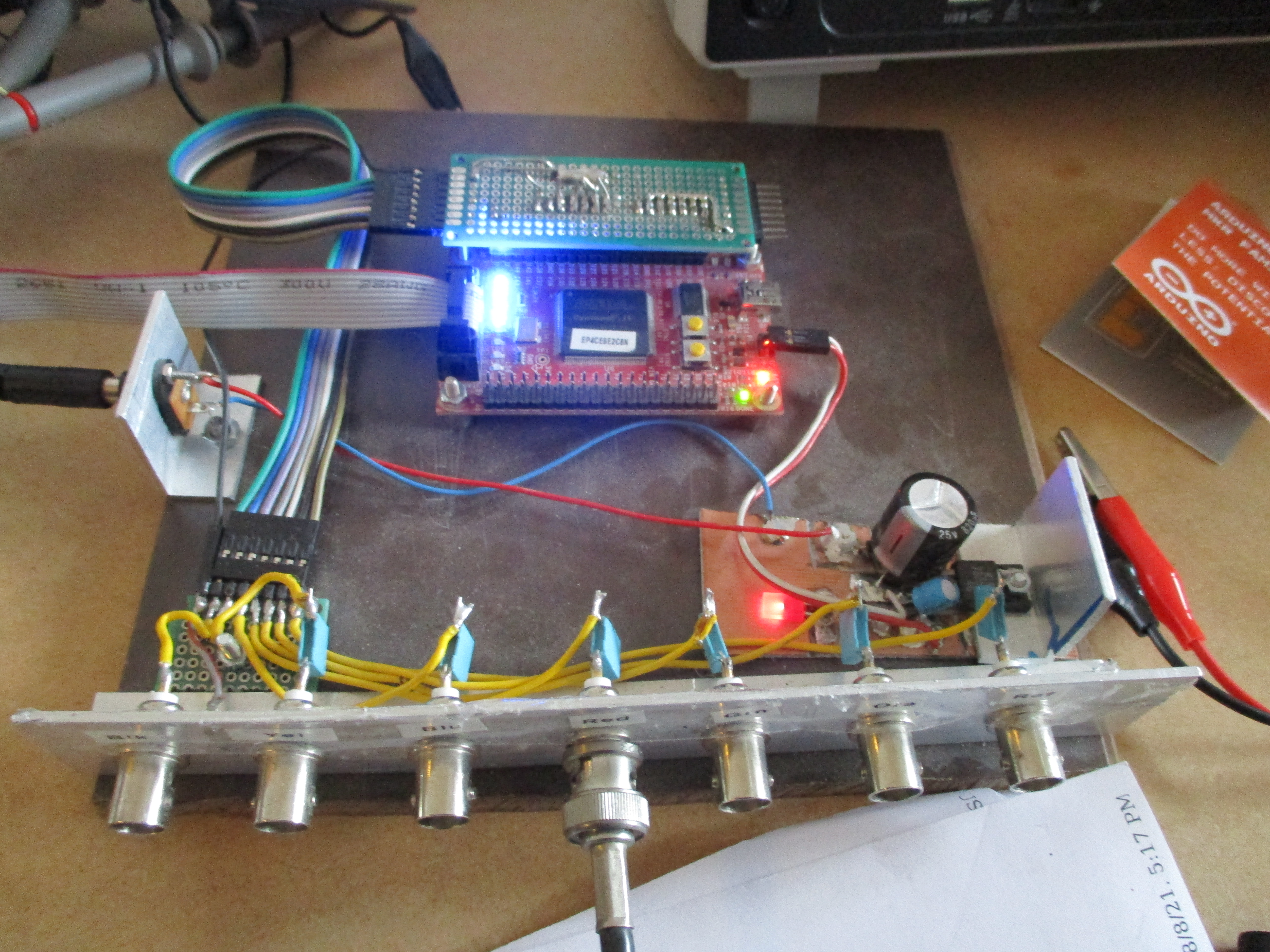 The FPGA based LORAN generator
|
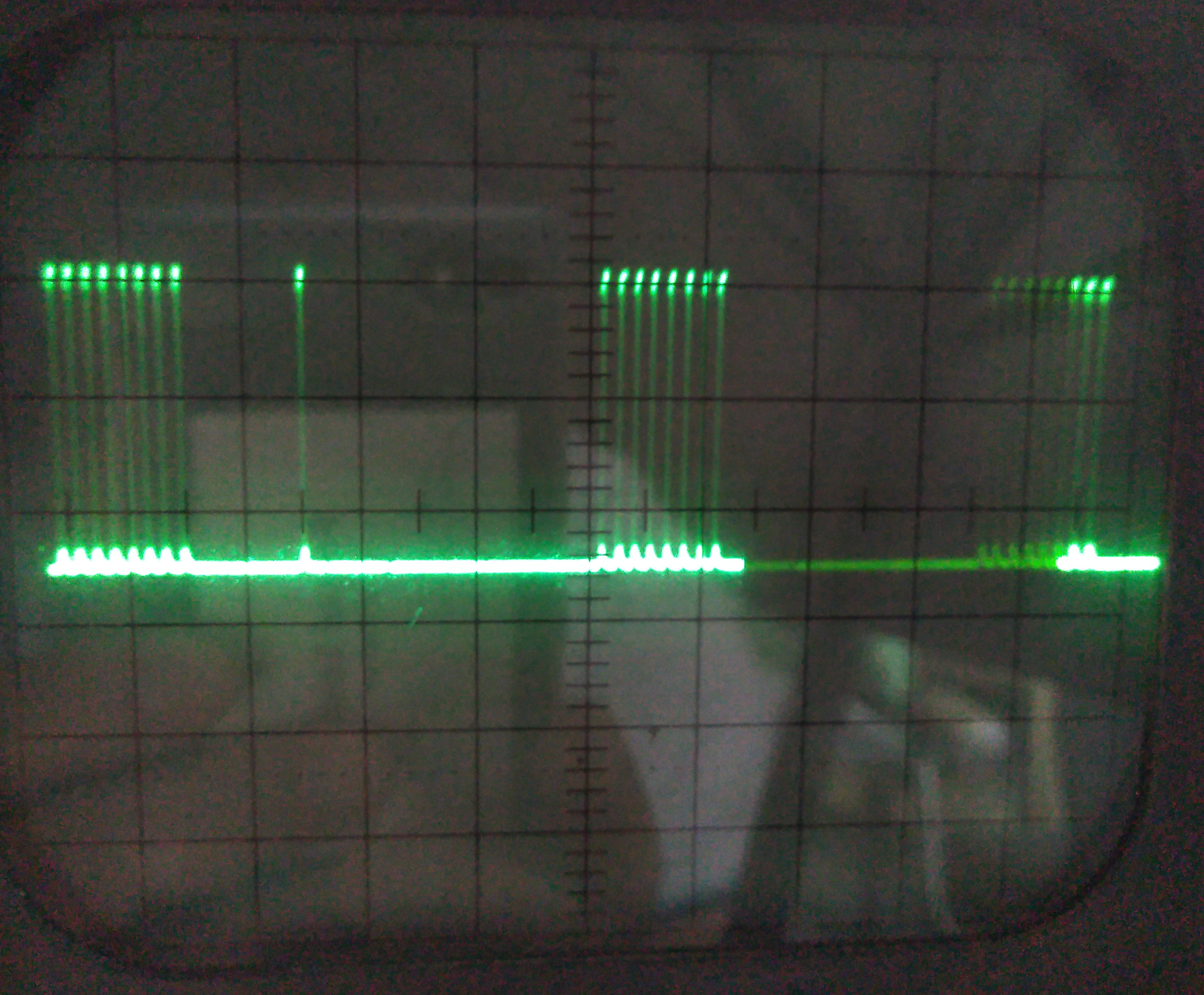 The output from the LORAN generator shown on a osciloscope
The extra master pulse clearly can be seen
|
PortArena : LoranChain Port Map
(
    PulseOut   => PortArenaPulse,
    GRISet     => 3712, -- 2H3   29700 Port Arena
    NrOfSlaves => 2,
    Master     => True,
    Sync       => Ref_Out,
    PulseClk   => PulseClkA
);

Red_Out  <= Ref100kHz  And GreatLakesPulse;
Grn_Out  <= Ref1850kHz And PortArenaPulse;
 Just an image while debugging
LORAN A Operation
While collecting old (useless) navigation equipment i was lucky to stumble on a LORAN A/C unit from the zeventies
branded Electronic Concepts ECI 105 AC, capable to display both Loran-A and C
It uses a CRT to display the signals that than had to be timed.
The such derived timings where used to find a hyperbolic line on a map such indicating the ships position.
Only much later when microchips became available this process could be done automaticly.
The unit i have rescued is verry heavy aproximate 40 kilo's even if it is all solid state.
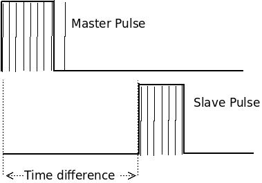
After some fidling with the knobs (no manual, no clue how to operate the machine),
i managed to determine the slaves time difference equivalent as produced by the generator.
This time difference indicated which hyperbole on the special LORAN-A map was one of the position fixes.
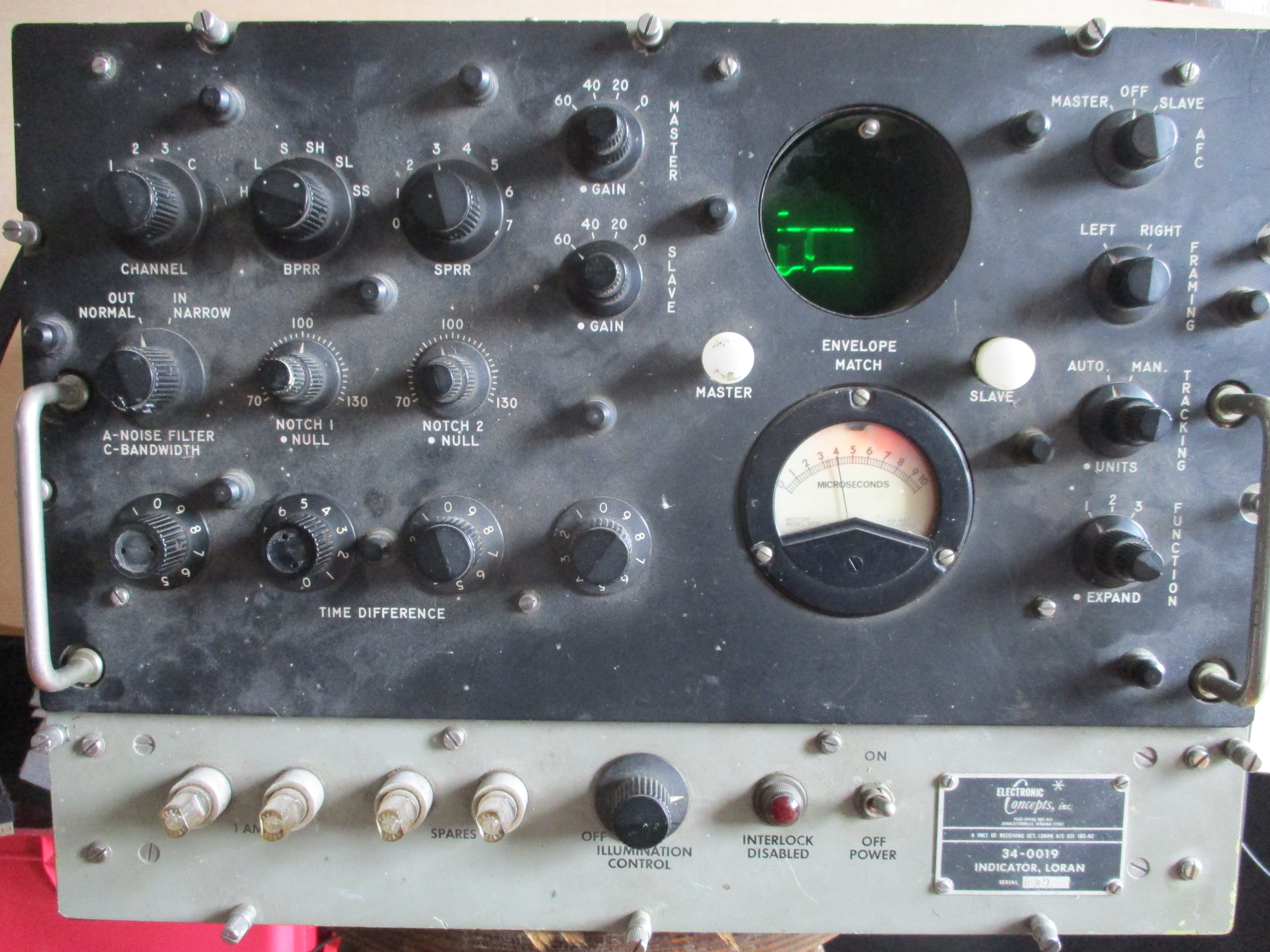 Verry rare and vintage Loran A and C receiver
|
 Detailed impression of the scope display
|
Loran-C Operation
In order to be able to bring the RF signal to the low impedance DC biased receiver input of most units,
i had to do some signal level conversion.
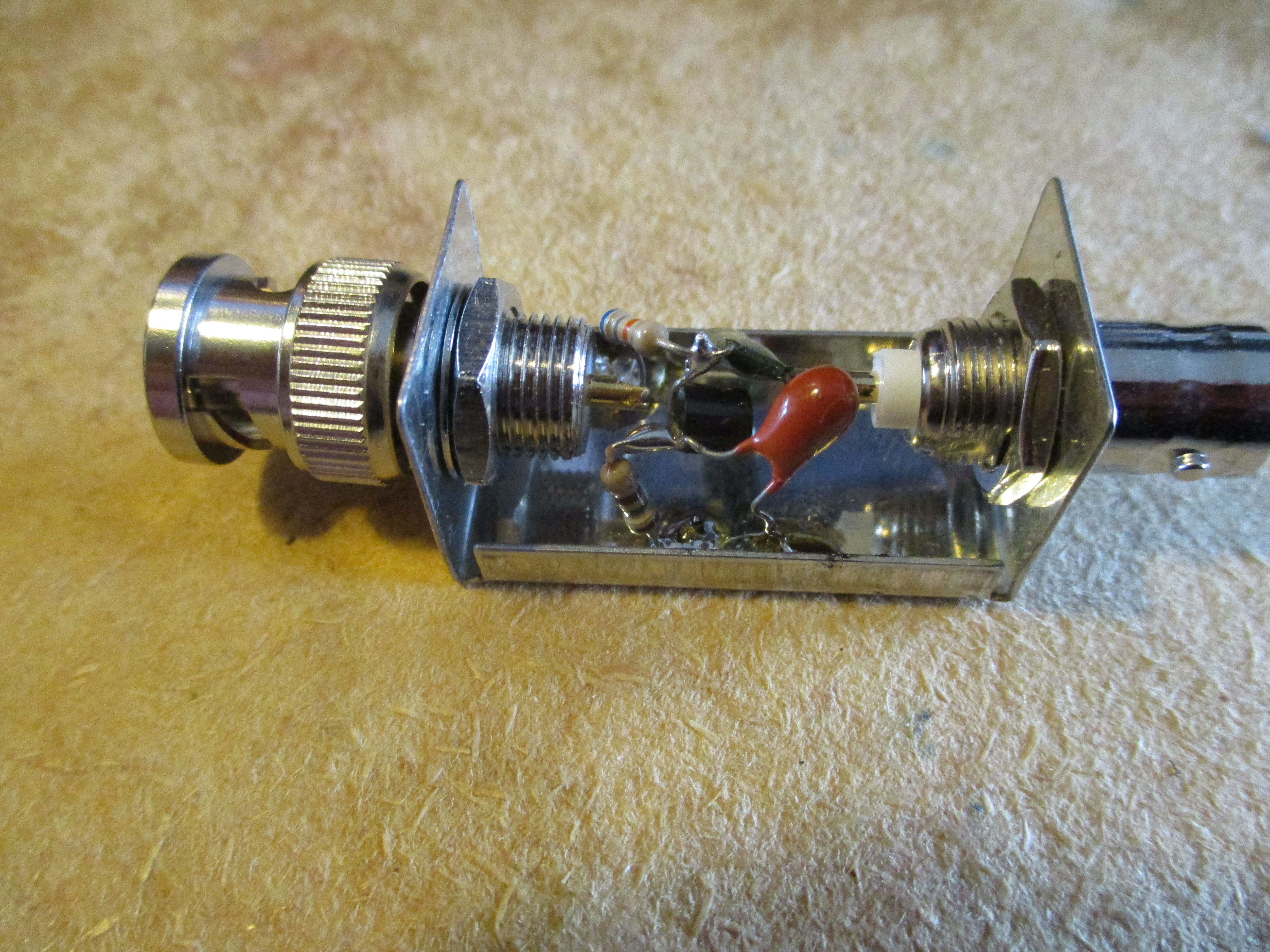 The signal coupler
|
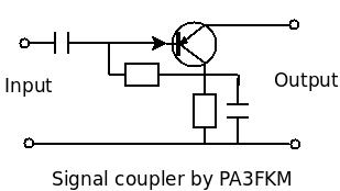 Schematics
|
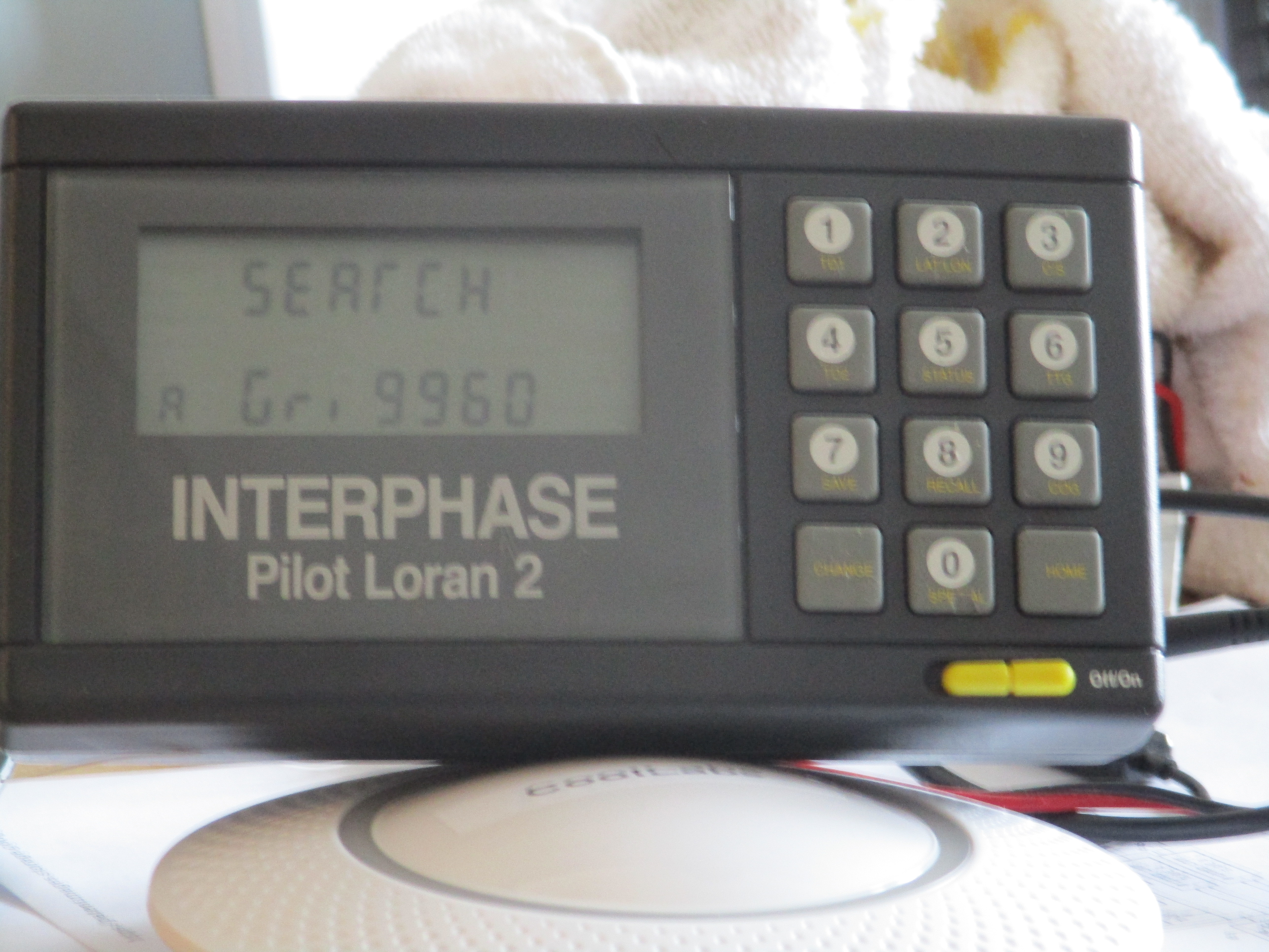 A LORAN-C unit from the ninetees
|
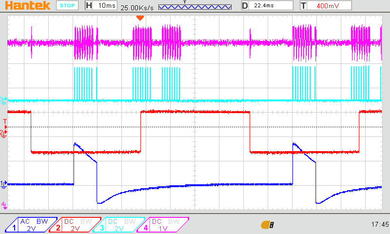
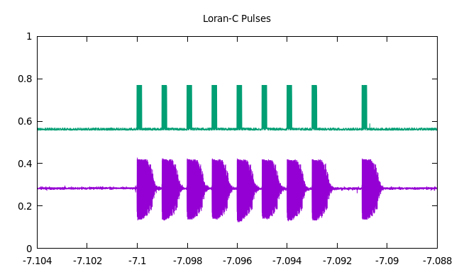 Green: Signal from generator
Purple: signal taken from the detector inside the unit
|
Aviation equipment